
After years, we’re still revisiting a new #GSoC proposal to implement #NURBS functions in #Blender, another ambitious project. I’m skeptical: wouldn’t it be better to leverage existing tools like FreeCAD’s #OCCT kernel and wrappers such as PythonOCC, which already provide ready-to-use solutions? A native implementation would require advanced mathematical and programming expertise, which a beginner (still learning C++) would struggle to master in just a few weeks of development. #b3d #CAD
Recent searches
Search options

#NURBS
0 posts0 participants0 posts today
A #CAD model made with #Plasticity by Kuechmeister Swagger a German user with great skill in Plasticity and #Moi3D #nurbs #surfacing #xnurbs #car
https://youtu.be/P0l--9Oxokk?feature=shared
youtu.be- YouTubeEnjoy the videos and music you love, upload original content, and share it all with friends, family, and the world on YouTube.


I've asked to #AI, an add-on to export #SubD to #NURBS from #b3d, the add-on managed to export something to both IGES and STEP, there are no errors, the exported files contain data structures but unfortunately any #CAD app managed to open those, although that seem like a failure, it's not, in fact it is the first time that I get an add-on that exports both in #IGES and in #STEP directly from #Blender without using external library, maybe next time I could be able to have a working add-on.
Continued thread
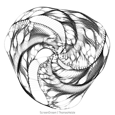
"Hilbert-Demons"
And another version with transparency, where some of the internal structures from the Hilbert Curve levels become visible...

"Hilbert-Demons"
Some years ago, I experimented in "Moment of Inspiration" with different levels of Hilbert Curves.
This is a NURBS-loft between those levels, going from low to high to low with the same distance between each.
We are looking from the top on the resulting structure.
And I always see two super-heroes or demons facing each other... ;-)
The rendering and texturing was done in Thea Render.

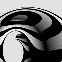
The classic #IonicScroll is the most complex of all components in the #IonicOrder mainly because it is poorly documented, if at all, and even poorly understood. It is as if the classical architects deliberately concealed its enigmatic design secrets within the confines of a smooth elegant shell that could only be revealed after intense study and analysis.
I got this impression because I spent years searching for credible and actionable documentation on how to recreate this beautiful design in a #CAD tool. In the Age of Internet and Social Media, my web searches always disappointed me because the results lacked something vital in one respect or another. Over the years, I created hundreds of versions of the scroll that looked so perfect and pleasing that I thought I had cracked it, only to find some flaw or another in my work.
So, it is with caution that I present my work on the scroll in the hopes that someone will build upon this knowledge and either validate the design, or correct it and share it with me and the rest of the world.
Looking back at my progress, I'm now surprised at how remarkably simple and elegant the design is that defied familiar geometrical construction techniques I had been using until now.
As I mentioned in my introductory post, this design can be recreated by drawing simple 2-dimensional lines and circular arcs, but instead of just #primaryProfileCurves, we will use up to three additional sets of curves — #secondaryCurves, #tertiaryCurves, and #quaternaryCurves — each derived from the previous set.
I extracted the #primaryCurves after a lengthy trial-and-error process that involved #curveFitting image scans from #Vignola’s book, #RegolaArchitettura. I had to #reverseEngineer the details because the measurements have either been lost, or are locked away in some library.
Even though we start with lines and arcs, the end results are always #NURBS curves and surfaces, but everything is done by the CAD tool, and no additional math is needed.

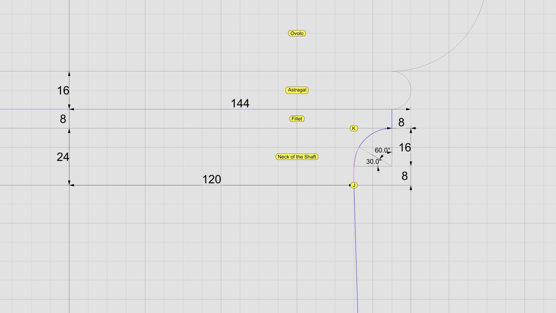
The section between points J and K is the #neck of the #shaft. The blue #primaryProfileCurve below J is the #interpolated #NURBS curve we fit through 8 points in https://pixelfed.social/p/Splines/791526497210906825.
The neck is conceptually divided into three bands, each 1 part (8 units) tall. In the top 2/3, we draw a circular 90° arc with radius of 16 units, divide it into thirds, and discard the lower 30° portion.
Then, blend the lower end of the arc and upper end of the interpolated NURBS curve to create a new NURBS curve shown here in magenta. Zoom in, and you will see that it deviates slightly from the original 90° arc. This is because the blended curve is tangential to the 60° arc and the longer NURBS curve. When joined, the three sections form a smooth continuously differentiable NURBS curve.
This level of precision is only needed for engineering work. If you just want a #charcoal #sketch, #draw in #ink, #paint in #watercolor, or even make #clay or #ceramic #basrelief, then you don't even need a #CAD program. A compass and protractor are sufficient. Just blend the shapes by hand as closely as you can. The imperfections, if any will be imperceptible.
This brings us back to the previous post. If you're not using CAD, how do you obtain the 8 points C through J using manual tools?
Look closely at the radiating lines, first of which passes through point B and the last one reaches point 8. An easy way to find the angle between these two lines is to use basic trigonometry.
Focus on the center of the arc, follow up to point 8, and then drop down vertically where the horizontal line is split at 120 units, and close back to the origin. This is a right triangle whose hypotenuse is the radius of the arc. The cosine of the angle between the base and the hypotenuse is 120/144 = 0.83333333. So the angle itself is arc cosine of 0.83333333, or 33.55730976°. For hand drawing, round it off to 33.6°. Then divide that into 8 parts of 4.2° each to plot points 1 through 8.
Here a little guide on how import a #IGES #Nurbs surfaces ready for Subdivision Modifiers, isn't always a suitable workflow, but can help maybe in some cases. #blender #b3d #Blender3D
https://blenderartists.org/t/how-import-iges-surface-topology-into-blender-ready-for-subd/1556580
Blender Artists Community · How Import IGES Surface Topology into Blender ready for SubDHow to import Nurbs surfaces into OBJ while preserving topology. introduction This is a short guide that allows you to import simple Nurbs models in IGES format into Blender, preserving the original topology of the surfaces with the original control cage, without having triangulated surfaces or NGons. Importing Nurbs surfaces with the same original topology allows you to use the subdivision surface modifier in Blender. This method can help in some cases but for complex objects it is advisab...
#Nurbs #Surface topology imported into #Blender without using add-ons to do the #retopology. It was a long job, also because I had to understand some things well, but with this method it is possible to import #CAD objects, and apply subdivision surfaces, in many cases the surfaces need to be reconstructed, but with #Moi3D it is quite simple. #b3d #blender3d


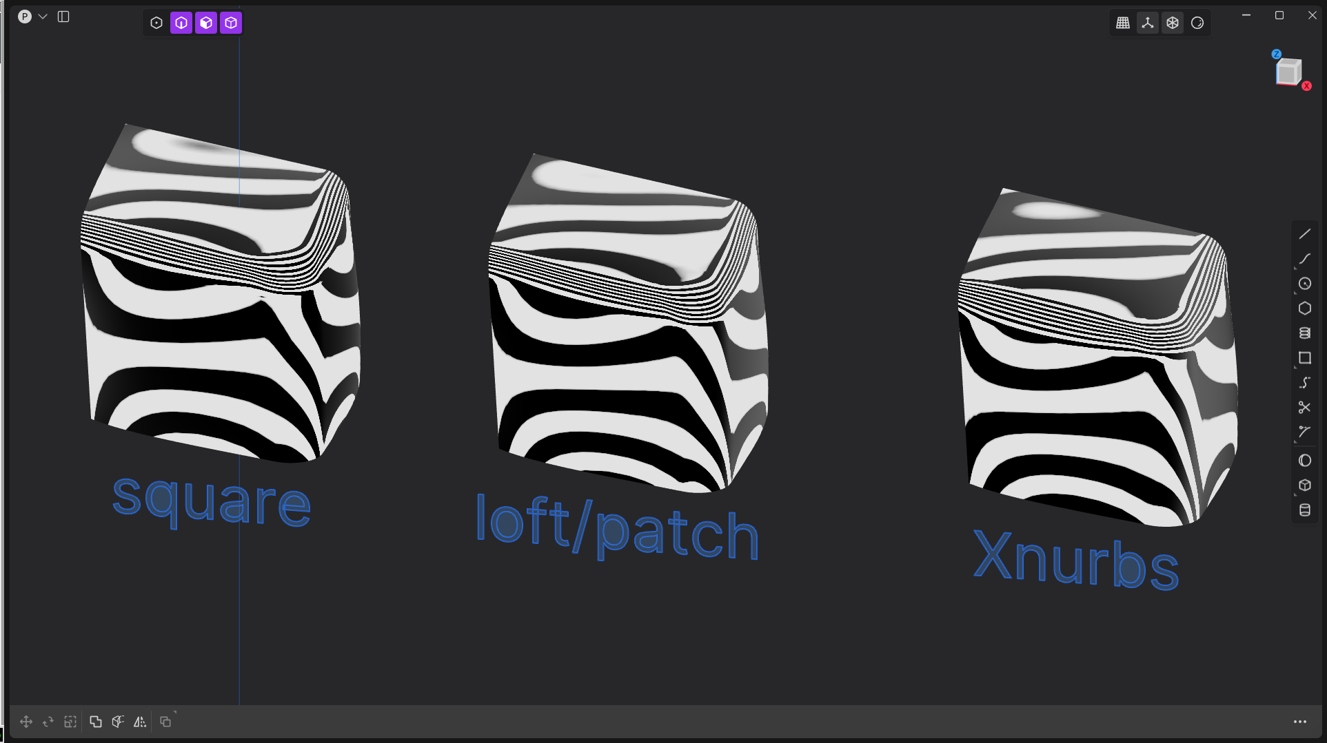
Many went crazy for #Xnurbs/square command, but with #Plasticity3D sometimes using the standard commands results in better surfaces, however, XNurbs creates simpler surfaces, but sometimes the CVs are a bit messy. #Nurbs #CAD
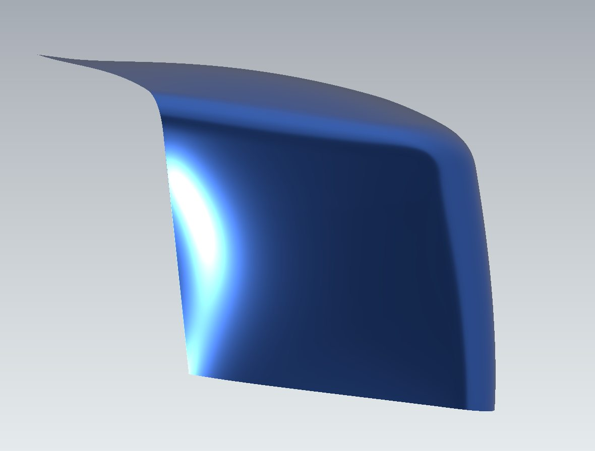
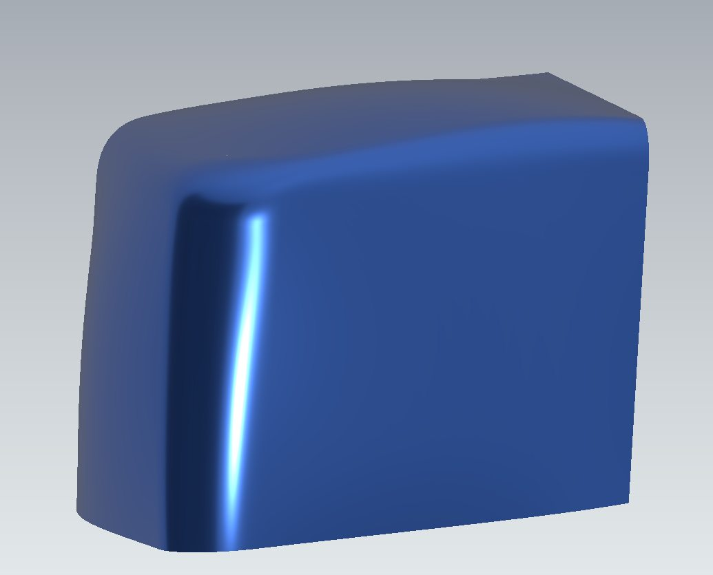
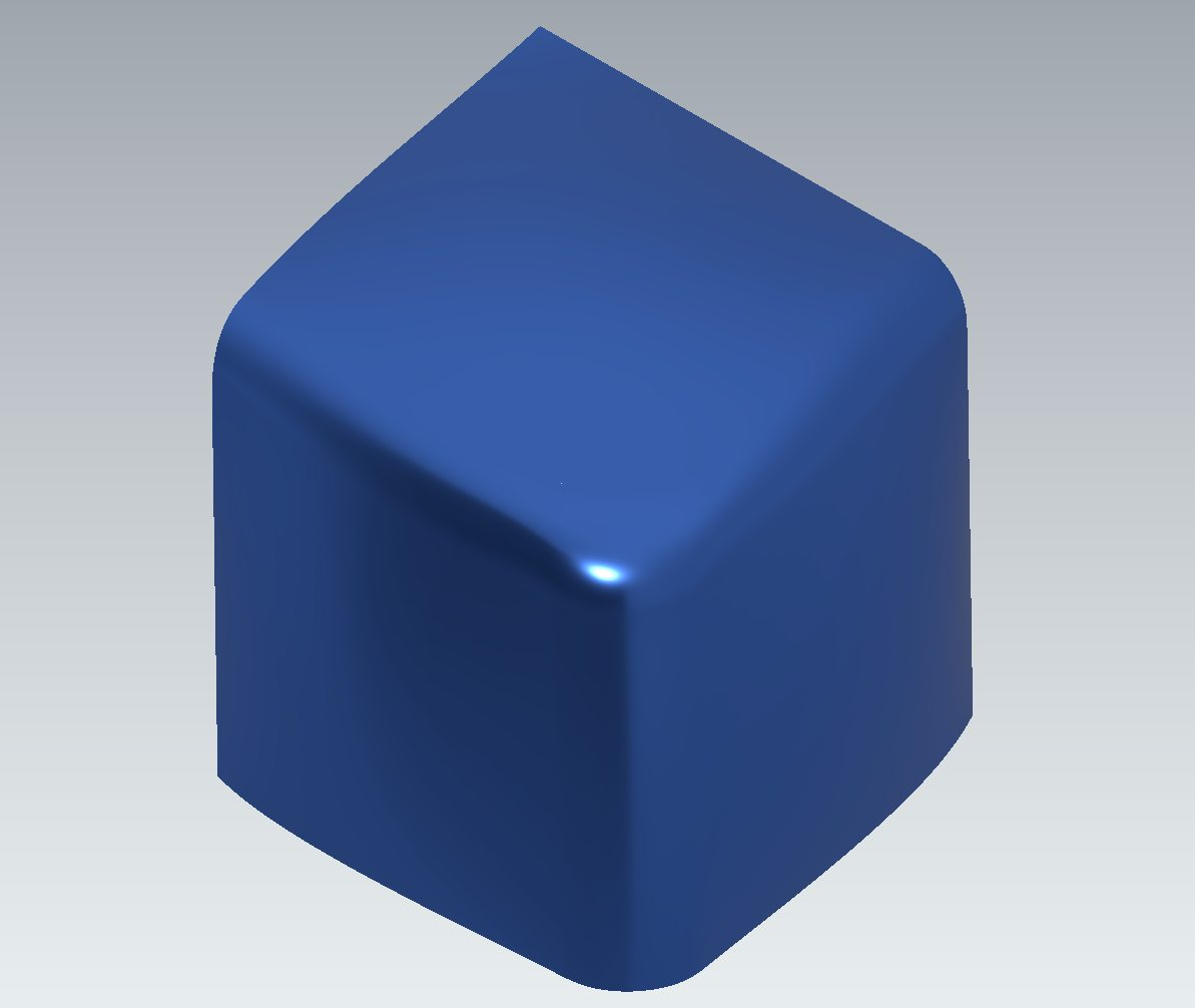
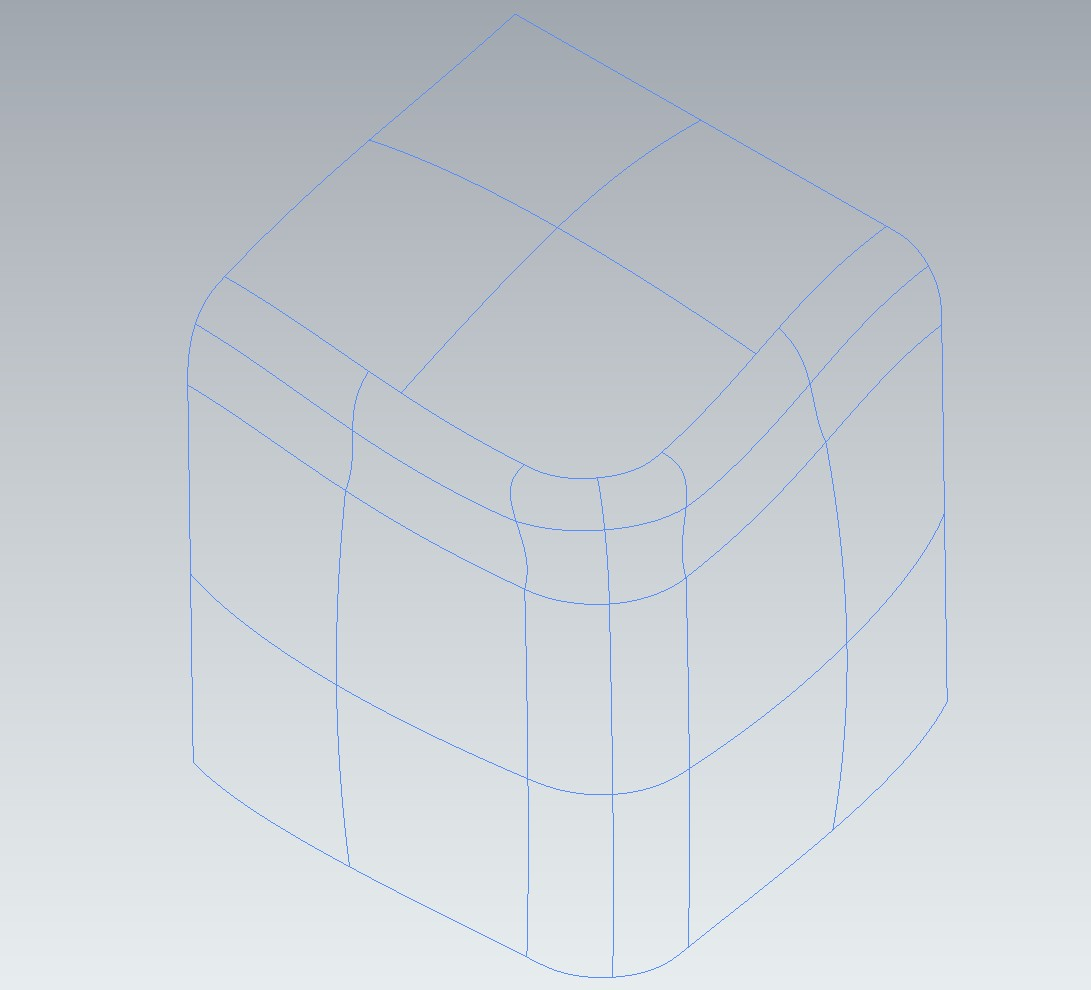
A corner ball patch, with two radius fillet and surfaces continuity G2. #NURBS #surfaces #CAD #Plasticity3D


Finished off my border code. Just about what I was aiming for; I don't want to spend a ton of time, but this looks nice and accomplishes the goal.

I wanted to make selecting curves visually distinct from selecting shapes.
A border outline seemed good, but generating that for a concave shape is very hard. So I'm going to generate the outline from the convex hull, which is relatively easy.
Honestly I'm feeling pretty awful and incompetent as a programmer today, but at least my attempt to implement the A. Melkman linear-time convex hull calculation of simple polygons worked on the first try!

A yellow cursor is touching it.")
I put some effort into handling the theoretical case of "infinite weights" for NURBS, and let me tell you, it produces some unusual results.
Mathematically it isn't very well-defined, but if you assume that infinite weight means "discard the influence of other points, only include this one," this is what you get.
The top and bottom control points of this shape have been set to infinite weight.

Now that looks nice. It doesn't look like "anti-aliasing," just smooth period.
I modified my engine so that it does everything in linear color. Simple and fast. I use a lookup table to convert colors.

Oh man, I am feeling so demotivated about my #NURBS project at the moment.
I thought doing the left edge was going to be relatively easy, but I have run into so many subtle issues.
... but I did just fix a couple of issues. Including a relatively big one related to not updating the previous point correctly.
But the multithreading part is still a big mess! I think that might just be one defect though.
Argh, this algorithm is so ill-posed. Knowing what I know now, I imagine I could come up with something far less flaky.
But anyway, it's almost working. I can even do this, where you don't see any glitches!
GIF
Lots of backend cleanup and fixes! The corruption in the cursor has been fixed.
I 'anchored' the bounds with a contour offscreen so that the glitch bleeds all the way across this time. 
GIF